ublo
bogdan's (micro)blog

bogdan » arduino: senzor de lumină cu led
11:20 am on Mar 25, 2018 | read the article | tags: hobby
în urma rugăminții profesorului Stamatin, de câțiva ani țin un curs la Facultatea de Fizică din Măgurele. dacă inițial numele «modelare și simulare» ascundea ecuații matematice și metode numerice, recent am înlocuit diferențialele cu Arduino, în ovațiile celor câtorva studenți care frecventează cursul. dotările limitate m-au făcut să devin creativ cu materialele de curs, iar rezultatul mi s-a părut suficient de interesant pentru a-l reproduce aici. așa că:
senzorii de lumină domină lumea simțurilor electronice. cu mici modificări, aceștia pot răspunde unei multitudini de întrebări, de la banalul ”e lumină afară?”, la ”ce culoare are un obiect?” sau ”la ce distanță am un obstacol în față?”. la prima vedere funcționează complex: un fragment de siliciu reacționează la lumina incidentă, modificând o mărime electrică. Einstein a luat premiul Nobel pentru explicarea principiului în 1921, deci trebuie să fie complicat. cu toate acestea, tehnologia s-a dezvoltat pe parcursul secolului care a trecut suficient de mult ca să putem reface experimentul în bucătărie.
materiale necesare:
- un Ardunio, de orice fel, în funcție de cât de familiarizat ești cu el; la curs l-am folosit pe ăsta (31 de lei);
- un led obișnuit, orice culoare și orice mărime, dar să fie un led simplu; știi că e un led simplu (30 de bani), dacă e foarte ieftin;
- două fire pentru a lega ledul la Arduino; mie îmi plac astea (3 lei), dar pot fi de orice fel;
puțină teorie:
un led este un dispozitiv semiconductor, de obicei din siliciu, al cărui element activ este vizibil. elementul activ poartă numele de joncțiune, adică locul de întâlnire pentru două materiale cu proprietăți diferite. ce e important de reținut pentru construcția de față este că cele două materiale formează un sandviș cu un mic spațiu între ele, asemeni unui condensator de la fizică. în funcționarea normală, trecerea curentului electric prin acel mic spațiu produce lumină. cu siguranță ai observat că polaritatea e importantă, deoarece lumina și circulația curentului se produc doar într-un singur sens.
ce se întâmplă în schimb când polaritatea e inversată? lipsa curentului electric duce la acumularea de sarcini electrice pe fețele sandvișului, încărcând condensatorul. cum naturii îi plac simetriile, orice rază de lumină incidentă generează perechi de sarcini, care se vor deplasa în direcții opuse, datorită atracției electrostatice. ajunse pe suprafețele sandvișului, acestea vor scădea sarcina acumulată pe condensator, scăzând proporțional și tensiunea electrică.

în mod normal, procesele se întâmplă extrem de repede și sunt extrem de mici ca intensitate. dar aici intervine genialitatea oamenilor care au proiectat Arduino: acesta e suficient de rapid și suficient de sensibil pentru a face față experimentului.
ce se va întâmpla:
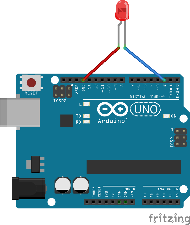
Arduino va încărca ledul, alimentându-l invers, după care va număra cât îi ia condesatorului format în jurul joncțiunii ledului pentru a se descărca. pentru a repeta experimentul de la curs, vei conecta ledul cu plusul (piciorușul mai lung, anodul) la GND (ground, 0V) și minusul (piciorușul mai scurt, catodul) la unul dintre terminalele Arduino, cu excepția pinilor 0,1 – care sunt responsabili pentru comunicarea serială și pinul 13, care are deja un led conectat intern și care te va încurca. eu am ales pinul 2.
în pregătirea Arduino, am definit un loc în memorie pentru stocarea informațiilor primite de la led. tipul de date folosit va fi întreg (int), numărând câte perioade de timp condensatorul a fost încărcat. pentru a fi accesibilă de oriunde, definiția se va afla în afara și înaintea celor două funcții speciale Arduino, setup și loop.
int value; // <- asa definesc un loc in memorie, int este tipul, iar value este numele
// pentru ca am definit-o în afara setup și loop, voi putea să o accesez de oriunde, prin nume
void setup() {}
void loop() {}
pentru citirea informațiilor, am folosit interfața serială a Arduino, care va fi inițializată prin:
int value;
void setup() {
  Serial.begin(9600); // <- aici initializez conexiunea seriala cu viteza de 9600 caractere / s
}
void loop() {}
periodic, am încărcat ledul pentru un interval de timp. experimental am ales 1ms.
int value;
void setup() {
  Serial.begin(9600);
}
void loop() {
  pinMode(2, OUTPUT); // <- aici definesc pinul 2 ca fiind pin de iesire
  digitalWrite(2, HIGH); // <- setez tensiunea pe pinul 2 la tensiunea de alimentare a Arduino
  delay(1); // <- astept 1ms, sa incarc condensatorul ledului
}
am măsurat în cât timp tensiunea la bornele ledului scade sub un anumit prag. aici aș fi putut să folosesc convertorul analog-digital din Arduino, dar în unele situații este prea lent. așa că am folosit proprietatea unui pin digital configurat ca intrare de a-și schimba starea în jurul jumătății tensiunii de alimentare a Arduino. astfel, dacă tensiunea la intrare scade sub 2.5V față de GND (pentru un Arduino alimentat la 5V), valoarea citită intern va fi LOW, în timp ce dacă tensiunea crește peste 2.5V, valoarea citită va fi HIGH.
pentru a determina în cât timp tensiunea la bornele ledului scade, am verificat la intervale scurte de timp dacă a scăzut. dacă a scăzut, trimit prin conexiunea serială valoarea înregistrată, altfel, mai aștept puțin timp și verific din nou. experimentând, am folosit ca timp de așteptare 40uS.
int value;
void setup() {
  Serial.begin(9600);
}
void loop() {
  pinMode(2, OUTPUT);
  digitalWrite(2, HIGH);
  delay(1);
  pinMode(2, INPUT);
  value = 0; // <- aici resetez ce stochez în memorie
  while(digitalRead(2) == HIGH) { // <- citesc pinul 2 si verific daca tensiunea depasește pragul
    delayMicroseconds(40); // <- daca e peste prag, lumina e prea slabă și aștept 40uS
    value = value + 1; // <- cresc cu o unitate valoarea stocată
  }
  // <- aici tensiunea la bornele ledului a scazut sub prag
  Serial.println(value); // <- așa că trimit valoarea prin conexiunea serială
}
în funcție de led și de condițiile de iluminare, valorile primite de calculator sunt uneori negative. acest lucru se întâmplă deoarece numărul de repetări depășește valoarea maximă care poate fi stocată într-un segment de memorie de tip întreg. pentru a preveni această situație, am introdus o limitare la 255 a numărului de cicluri pentru care verificarea are loc:
int value;
void setup() {
  Serial.begin(9600);
}
void loop() {
  pinMode(2, OUTPUT);
  digitalWrite(2, HIGH);
  delay(1);
  pinMode(2, INPUT);
  value = 0;
  while((digitalRead(2) == HIGH) && (value < 255)) { // <- verific în plus dacă valoarea stocată e sub 255
    delayMicroseconds(40);
    value = value + 1;
  }
  Serial.println(value);
}
note de final:
ledul este sensibil la același tip de lumină pe care o emite. folosind acest principiu, poți foarte ușor să-l transformi într-un senzor de culoare. de asemenea, un led are de obicei o lentilă care dirijează razele de lumină, limitându-i astfel câmpul vizual, la fel ca în cazul emisiei. folosind această informație, poți adapta foarte ușor un led pentru a măsura distanța.
bogdan » raspberry pi minimal gentoo (updated)
03:46 pm on Dec 29, 2013 | read the article | tags: hobby, raspberry
the love for gentoo and the spare time during this winter holidays made me update my minimal raspberry pi gentoo image. the image includes:
- latest 3.10.y (3.10.25+) raspberry pi kernel (sha1: 035642b95ebe820cc265070af72a13f4fa1eb4c7). hdmi output is enabled, also the sound card module is compiled together with lan95xx driver, zd1211 usb wi-fi driver, 3g modem support, ftdi serial addapter and f2fs support. of course gpio. f2fs-tools are also included, but the root partition is still ext4 as some still use debian stable which has no f2fs support.
- iproute2, iptables and dropbear ssh for networking. no ipv6 support as i think rpi is best suited for local networks. udhcpc is provided through busybox. same ping.
- full blown vim and wget. i like editing in colors. and sometimes you have to download something.
- lighttpd http server. as i’m starting to like how easy it is to setup. the root folder of the http server is on the VFAT partition, under www. so you can upload your website files directly from windows.
- php5.5.4 with fpm and sqlite3. although minimal things are compiled in php, it should be enough to run wordpress. warning! no gd or imagemagick support.
- wpa_supplicant if you decide to add an wifi dongle. pulled out onto the /boot VFAT partition the network configuration file under /boot/etc/network.
- you need at least 2Gb of SD card. had incredible success with Hama 8Gb/Class 10/Blue cards. the Verbatim 8Gb/Class 10/Blue card on which i built the first version doesn’t work anymore.
- root password is blackcat
here’s the download link. enjoy! =) gentoo-3.10.25-blackcat-1.0.img.gz (sha1: d5560f81e43361a7e99db6e7d42e67d4446b0b7b)
![]()
bogdan » raspberry pi minimal gentoo (details)
12:11 am on May 3, 2013 | read the article | tags: hobby, raspberry
a few details on running gentoo-3.8.8-cat-0.8.img.gz on your raspberry pi:
- lacking a hwclock, the openrc will complain about the skew clock of some files. use touch to fix their clock and rc-update -u to update the openrc deptree. a reboot will show no more complains.
- above is one of the reasons net.wlan0, sshd and lighttpd are not added by default to the “default” runlevel. more, the net.wlan0 symlink is missing. use ln -s /etc/init.d/net.lo /etc/init.d/net.wlan0 before running rc-update add net.wlan0 default. same for eth0.
- to make it easier to configure the net, both /etc/wpa_supplicant/wpa_supplicant.conf and /etc/conf.d/net are linked in /boot/config/wireless.txt and /boot/config/network.txt respectively. you can edit those from windows (while creating the bootable SD card).
- the kernel contains a fix that enables the nat table in iptables. who knows, a pi router might be a nice idea.
- you can login via serial console =). it should be interesting connecting a serial LCD to see it.
- also, lighttpd is pre-configured to use files in /www directory. there, each .rb file is parsed as a cgi script. i’ve minimized the config so it fits only .rb, .html, .js, .css., .jpg, .png files. more than enough in my opinion.
- the linux includes pi_piper to access pi’s GPIO. including the SPI.
i’m thinking to build an arduino interface to protect the pi’s GPIO and to extend the functionality using the serial port. don’t know when i’ll have time to do that, but it’s in my plans.

bogdan » raspberry pi minimal gentoo
09:58 pm on Apr 28, 2013 | read the article | tags: hobby, raspberry
i love gentoo. mostly for its ability to be small and tight on the machine running it. so, here it is. a small gentoo distro (around 121Mb) that includes the following:
- iproute2 & iptables (no ipv6 though, cause i don’t really like it)
- vim & wget
- lighttpd (wanted nginx, but has some problems with minimum arm cross-compile)
- openssh (wanted dropbear, but same as above)
- ruby (wanted python, but same as above)
- reiserfs root, tools and kernel support (be it as it may, reiserfs is still a damn good file system in my opinion)
- wpa_supplicant for wifi configuration
- update (0.4): fixed ruby socket bug
- update (0.6): fixed ruby ffi_c.so problem (gentoo doesn’t cross compile C extensions from ruby gems ebuilds. soon a post on a workaround). also added a full blown vim distribution: syntax and advanced commands support. added around 22Mb. you can still use the slim 0.4 version, but you have to replace ffi_c.so with this one (sha1: 07e000d78fd8af57c40a47a26dfd685092d03982)
- root password is raspberrypi
the kernel:
- 3.8.8 latest (3.8.y / last night fetched) raspberry pi patched kernel configured with usb LAN95xx network driver (default) and ZD1211 driver (for a USB WiFi SMC dongle i have) with firmware
- for convenience, you get the imagetool-uncompressed.py on the /boot partition
downloads:
- the updated raspberry pi 1Gb img file (including updated vim and a working pi_piper with an example.rb): gentoo-3.8.8-cat-0.8.img.gz (sha1: efe34f9c3c5dbd572f83884e9ef0e76136cecb4d)
- the raspberry pi 1Gb img file (ready to be “burned” on an SD card): gentoo-3.8.8-cat-0.4.img.gz (sha1: 5fe996882533bfd3474bc199e6ee4f124e0f1f52)
- the kernel image: kernel.img (sha1: cf2bcc30bc3da9c5d6d55c8c4d9a83cf7f43e928)
- the kernel .config (as the bcmrpi_defconfig isn’t bootable): config (sha1: a524301b9818e11909206584f2710993c2dbc0d0)
references:
- dustin c. hatch, minimalist gentoo for raspberry pi
- xec design > raspberry pi qemu insights (warning! couldn’t build a bootable qemu kernel, probably because of my qemu version, but could test my build against their kernel.img)
- raspberry pi github (firmware, kernel sources, etc.)
- linaro (tried their 3.9.x kernel which seemed well ahead, but had problems with the compiler)
![]()
bogdan » pic32-pinguino-otg enc28j60 example
11:10 pm on Nov 1, 2012 | read the article | tags: hobby
 for a week or so i’m searching the internet for a simple example (that can be easily expanded) on how to use the pic32-pinguino-otg with a UEXT connected enc28j60 module (both from olimex). and of course i didn’t wanted to use the “universal” microchip tcp/ip stack that requires MPlab. after digging quite a lot trough the pinguino repositories, i managed to compile a set of working header files (which you can find here) and a small program from which you can ping your boards. for the library to work, copy it under %pinguino/p32/include/pinguino/libraries/ethernet, where %pinguino is the path to your pinguino installation folder. i used pinguino X.3 and it compiled fine.
/*-----------------------------------------------------
Author:  --<>
Date: 28/Oct/2012
Description:

-----------------------------------------------------*/
#include <ethernet/ip_arp_udp.h>
#define BUFFER_MAX    224

static u8 buf[BUFFER_MAX+1]; // the received message
u16 len; // the length of the received messages

void setup() {
	// put your setup code here, to run once:
	// this is the enc28j60 ip address
	u8 myip[4] = { 192, 168, 2, 2 };
	// this is the enc28j60 mac address
	u8 mymac[6] = { 0x02, 0x04, 0x08, 0x10, 0x12, 0x14 };
	init_ip_arp_udp (mymac, myip);
	enc28j60Init (mymac);
	}

void loop() {
	len = enc28j60PacketReceive(BUFFER_MAX, buf);
	CDC.printf("received! len: %d\n", len);

	if (len == 0) {
		return;
		}
	if(eth_type_is_arp_and_my_ip(buf, len)) {
		make_arp_answer_from_request(buf, len);
		return;
		}
	if(eth_type_is_ip_and_my_ip(buf, len)==0) {
                return;
                }

	if(buf[IP_PROTO_P]==IP_PROTO_ICMP_V && buf[ICMP_TYPE_P]==ICMP_TYPE_ECHOREQUEST_V) {
		// the ping reply
		make_echo_reply_from_request(buf, len);
		return;
		}
	}
bogdan » cheap low power PIR sensor
09:12 pm on Sep 23, 2012 | read the article | tags: hobby
recently i had a problem. i needed to build a wireless PIR sensor that could be powered by a LiPo 1400mAh battery. seems like a lot of juice, but thinking that the wixel draws usually almost 30mA and a mangled PIR sensor 8mA, the sensor would have to be recharged every 1.5 days. not a practical approach. through some neat hack i managed to send the wixel in sleep mode, making it draw less than 100uA, but still had the power hungry PIR sensor.
today i managed to solve this problem also. using a cheap (~$15) PIR sensor with a nice housing and a few components i managed to bring the PIR sensor as low as 1.6mA (measured), making the battery last for 34 days. here’s how:
first remove the PIR element. it’s quite big component, encased in metal and with a window for sensing IR radiation. be careful when removing it as it is quite a sensitive component! then gather the components and build this schematic:

components list:
IS1 is the PIR element. this component was on my Eagle library and matched the dimensions of the one i recovered.
R1, R3 = 47K
R2 = 18K
R4, R8 = 1M
R5 = 1K
R6, R7, R9 = 100K
R10 = 330K
C1, C7 = 10uF (there is no mistake! C7 is 10uF but can be polarized. i used tantalum capacitors)
C2, C3 = 4.7uF
C4, C5, C6 = 10nF
IC1A, IC1B = TL082
JP1 = a 3 pin connector in which 1 = +3V3, 2 = signal (connect to wixel P1_0), 3 = GND
JP2, JP3, JP4 = 2 pin connectors as there’s always a good idea to serve power to other devices
notes:
the R9, R10, C7 group sets the sensitivity of the PIR sensor. this setup worked for what i wanted but trust me, it took about 3 hours of testing to get to those values and configuration. the interrupt on P1_0 of the wixel should be configured for raising edge, not falling. R10 is needed to lower the IC1B output potential below the interrupt threshold. an IR event sends the IC1B output close to 3.3V followed by a drop to almost 0V then back to almost 1.65V (this is the value you should have when idle). with R9/R10 the idle voltage is close to 1.26V making the interrupts stable. setting R10 higher, moves this point close to 1.65V when the interrupts are unstable. making it lower decreases the sensitivity. i don’t recommend getting under 56K (standard value) as the interrupts cannot be triggered anymore.
bibliography:
i drew inspiration from Micropik’s D203B PIR element datasheet.
bogdan » wixel PM3 low power sleep mode (CC2511F32)
10:18 pm on Sep 22, 2012 | read the article | tags: hobby
don’t know if you have any idea what this is, but i love the wixel. it’s a CC2511F32 based device that works basically like every arduino except that it has a embed wireless transceiver. i got mine from watterott. the wixel is a nifty little device, good for connecting sensors to a PC, both wired and wireless. the problem for the wireless approach is that the device is power hungry 30mA is quite a lot for a battery powered app. but luckily, CC2511F32 is made by texas instruments that addressed this issue: it has a sleep mode in which it consumes less than 1uA.
here’s a small code i’ve wrote to test this sleep mode, based on blink led. it blinks the led 10 times, then powers down and waits for a falling edge on P1_0 (remember to connect this pin with a resistor to 3V3 in order to make the device sleep, otherwise P1_0 is quite sensitive).
#include <wixel.h>
#include <usb.h>
#include <usb_com.h>
#include <stdio.h>

int32 CODE param_blink_period_ms = 500;
int32 CODE param_count = 20; // counting 20 changes of the red led state, then go to sleep
uint32 count = 0; // the actual counter

uint32 lastToggle = 0;

/* catch interrupts on P1INT					*/
ISR (P1INT, 0) {
	/* clearing the CPU interrupt registers			*/
	/* 1. first the general interrupt register, IRCON2	*/
	IRCON2 &= ~0x08;				// clear IRCON2.P1IF
	/* 2. followed by the P1 interrupt register, P1IFG	*/
	P1IFG &= ~0x01;					// clear P1IF0
	/* not related to the interrupt itself, but to the	*/
	/* sleep mode: clear SLEEP.MODE flag			*/
	SLEEP &= ~0x03;					// clear SLEEP.MODE
	/* disable interrupt only for P1_0			*/
	P1IEN &= ~0x01;					// clear P1_0IEN
	/* wait, disabling interrupts on P1 also :)		*/
	IEN2 &= ~0x10;					// clear IEN2.P1IE
	}

/* the function that puts the system to sleep			*/
/* i've chosen PM3 as i don't need a timer wake-up event	*/
void putToSleep () {
	/* make the P1_0 a input pin				*/
	P1DIR &= ~0x01;					// P1_0DIR = 0 -> input
	/* clear any interrupt flags. see above for details	*/
	IRCON2 &= ~0x08;				// clear IRCON2.P1IF
	P1IFG &= ~0x01;					// clear P1IF0
	/* set the interrupt enable flag on P1_0		*/
	P1IEN |= 0x01;					// P1_0IEN = 1;
	/* set the type of interrupt: 0=rising edge; 1=falling	*/
	PICTL &= ~0x02;					// PICTL.P1ICON = 0
	/* set the interrupt enable flag for the entire P1	*/
	IEN2 |= 0x10;					// IEN2.P1IE = 1;
	/* enable global interrupts				*/
	IEN0 |= 0x80;					// IEN0.EA = 1;
	/* the sleep mode i've chosen is PM3			*/
	SLEEP |= 0x03;					// SLEEP.MODE = PM3
	/* idling the CPU - required in the manual		*/
	if (SLEEP & 0x03) PCON |= 0x01;	// PCON.IDLE = 1;
	}

void updateLeds()
{
    usbShowStatusWithGreenLed();

    LED_YELLOW(0);

    if (getMs() - lastToggle >= param_blink_period_ms/2)
    {
        LED_RED(!LED_RED_STATE);
        lastToggle = getMs();
		/* the piece of code that counts and if the counter	*/
		/* hits the limit, puts the system to sleep		*/
		count++;
		if (count == param_count) {
			count = 0;
			/* here the blinking freezes, waiting for a	*/
			/* falling edge on P1_0				*/
			putToSleep();
			}
    }
}

void main()
{
    systemInit();
    usbInit();

    while(1)
    {
        boardService();
        updateLeds();
        usbComService();
    }
}
bogdan » webstock 2012
09:22 pm on Sep 18, 2012 | read the article | tags: hobby
pentru prima dată voi participa la un eveniment dedicat online-ului. webstock 2012. am primit chiar astăzi invitația de la cristian manafu. m-am înscris din curiozitate și din dorința de a cunoaște (cu puțin noroc) personal oamenii ale căror gânduri le citesc în fiecare dimineață. revin cu detalii.
bogdan » pinguino / manchester decoder / opentherm
09:28 pm on Jul 29, 2012 | read the article | tags: hobby
as a part of my PhD. studies i needed a simple interface to a central heating unit (CHU). searching the internet i found that most CHU are slave devices that use OpenTherm protocol for communication. i will bother you with that in a future post. for now, OpenTherm uses the Manchester code for sending and receiving information. as recently i’ve switched from arduino to pinguino (still using arduino for my work with students), here’s a small library that i use to decode the OpenTherm messages, that is versatile enough to be used for any Manchester code codec. it worked with a PINGUINO MX220 from Olimex. the tolerance for the bit timing is quite good: it correctly received data with bit lengths from 880uS to 1320uS. for other ranges tweak the defined constants.
// the code bellow is provided "as-is" with no warranty whatsoever
// also, this is a sketch and should be treated likewise

/* half the bit length */
#define OTHRM_BIT_TX0    500
/* threshold in microseconds for bit detection.
   it should be larger than the fastest transition time,
   yet it should consider the clock tolerance and the
   speed of the CPU. for PINGUINO 32MX220 this worked */
#define OTHRM_BIT_RX0    300
/* maximum length of a bit, in microseconds */
#define OTHRM_BIT_RX1    1000

#include <delay.c>

/* the OpenTherm frame has 32 bits. for 8 bit processors, use an array */
volatile u32 OTHRM_FRAME;

/* this function sends the OTHRM_FRAME data through "pin" */
void othrm_tx (u8 pin) {
    u8 c = 0;

/* start bit "1" of OpenTherm */
    digitalWrite (pin, HIGH);
    Delayus (OTHRM_BIT_TX0);
    digitalWrite (pin, LOW);
    Delayus (OTHRM_BIT_TX0);

/* actual data */
    for (c = 0; c<32; c++) {
        if ((OTHRM_FRAME >> 31) == 1) {
            digitalWrite (pin, HIGH);
            Delayus (OTHRM_BIT_TX0);
            digitalWrite (pin, LOW);
            Delayus (OTHRM_BIT_TX0);
            }
        else {
            digitalWrite (pin, LOW);
            Delayus (OTHRM_BIT_TX0);
            digitalWrite (pin, HIGH);
            Delayus (OTHRM_BIT_TX0);
            }
        OTHRM_FRAME <<= 1;
        }

/* stop bit "1" of OpenTherm */
    digitalWrite (pin, HIGH);
    Delayus (OTHRM_BIT_TX0);
    digitalWrite (pin, LOW);
    Delayus (OTHRM_BIT_TX0);
    }

/* receiving data from pin "pin". the data will be found in
   OTHRM_FRAME */
void othrm_rx (u8 pin) {
    u8 s = 1, c = 0;
    u16 m = 0, t = 0;
    OTHRM_FRAME = 1;

/* wait for the begining of the start bit. i need this.
   for non-blocking operation you should include a timer
   with a timeout. */
    while (!digitalRead(pin));
    for (c = 0; c<33; c++) {
        OTHRM_FRAME <<= 1;

        t = 0;
        while ((s == digitalRead(pin)) && (t < OTHRM_BIT_RX0)) { t++; Delayus(1); }
        s = digitalRead(pin);
        OTHRM_FRAME |= !s;
        t = 0;
        while ((s == digitalRead(pin)) && (t < OTHRM_BIT_RX0)) { t++; Delayus(1); }
        s = digitalRead(pin);
        }
    }
bogdan » a bunch of sensors
12:15 pm on Jan 28, 2012 | read the article | tags: hobby
i’ve got a bunch of sensors form my PhD. thesis. i won’t bother you with the details =). unfortunately i wasn’t very inspired in my choosing and i ended up with a bunch of accurate, but hard to access sensors. the ones i’m talking about are MPL115A1, SHT15 and TSL230R all from my favorite provider watterott.
i’ve roamed the internet for a while to find myself some Arduino libraries to access the sensors but failed to find what i wanted. so here’s what i came up with MPL115A1 Arduino library, SHT15 Arduino library and TSL230R Arduino library. the code is provided “as-is” and the work is based on roaming drone’s TSL230R tutorial, jim lindblom’s sparkfun MPL115A1 example code and nathan seidle’s sparkfun SHT15 example code.
tomorrow i’ll update this post with an example code and some wiring diagrams.
find me:
in my mind:
- #artist 2
- #arts 4
- #away 3
- #bucharest 1
- #buggy 6
- #business 1
- #clothes 1
- #comics 1
- #contest 3
- #dragosvoicu 1
- #education 1
- #food 2
- #free-ideas 1
- #friends 14
- #hobby 23
- #howto 9
- #ideas 33
- #life lessons 4
- #me 59
- #medium 4
- #mobile fun 4
- #music 51
- #muvis 17
- #muviz 13
- #myth buxter 1
- #nice2know 15
- #night out 1
- #openmind 2
- #outside 3
- #poems 4
- #quotes 1
- #raspberry 4
- #remote 56
- #replied 51
- #sci-tech 7
- #sciencenews 1
- #sexaid 7
- #subway 39
- #th!nk 5
- #theater 1
- #zen! 4